1
📝 Product Overview
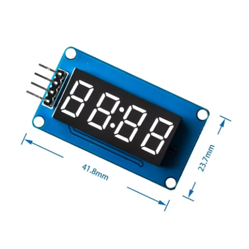
The module consists of a 4-digit numeric display with a center colon, making it perfect for clock or timer applications. On the back, it features the TM1637 driver chip, which handles the multiplexing so your microcontroller doesn't have to. 🕒
⚙️ Technical Specifications
- Driver Chip: TM1637 (Handles all display scanning and driving). 👾
- Display Type: 0.36-inch 4-digit common anode 7-segment display (with center colon). 💡
- Operating Voltage: 3.3V to 5V DC (Compatible with Arduino, ESP32, and Raspberry Pi). ⚡
- Communication: 2-Wire Serial Interface (CLK and DIO). 🔗
- Dimensions: 41.8mm x 23.7mm (as shown in your image). 📏
- Mounting: Features 4 M2 screw holes for easy installation in cases or panels. 🛠️
📌 Pinout Description
The module has a 4-pin header for simple wiring:
- CLK: Clock input pin. ⏱️
- DIO: Data Input/Output pin. 📤
- VCC: Power supply (3.3V - 5V). 🔴
- GND: Ground connection. ⚫
🌟 Key Features
- Adjustable Brightness: The driver chip supports 8 levels of software-controlled brightness. 🔅
- Minimal Pins: Unlike raw 7-segment displays that require 12+ pins, this module only needs 2 digital pins from your MCU. 🤏
- Clear Visibility: High-contrast LEDs that are easy to read from a distance. 👀
🚀 Example Library
For Arduino users, the most stable and widely used library is the Avishay Orpaz TM1637 Library. 📚
GitHub Reference: https://github.com/avishorp/TM1637/blob/master/examples/TM1637Test/TM1637Test.ino
Note:
while the interface looks like I2C, it is actually a specific 2-wire protocol. you should use the dedicated TM1637 library rather than standard I2C scanners to detect it. 💡